
- Thank you received: 0
Create an Angenent Torus with high accuracy
4 years 6 days ago - 4 years 6 days ago #4030
by Jiashun
Create an Angenent Torus with high accuracy was created by Jiashun
Hi all,
I am working on a project concerning the meaning curvature flow of a 2d closed surface. Now I am going to perform a numerical test on a rotational geometry which is known as the Angenent Torus, whose profile curve (which is not a circle) can only be numerically computed.
I generate the geometry following this post: Rotationally symmetric geometries .
Thus, I only need to approximate the profile curve in cubic splines.
I choose the control points by guessing:
FIrst I add several nodes of the profile curve, then I compute the intersection of the tangent lines of two adjacent nodes as the additional control nodes.
For example, A1, A2 are two adjacent nodes and I choose B1 as the intersection of their tangent lines. Then I add a cubic spline for example by geo.Append(["spline3",A1,B1,A2]).
I approximate the profile curve by about 40 piecewise cubic splines. (I think more pieces can give high accuracy?) and generate the high order isotropic finite element by using
mesh.curve(2)
and
fes = H1(mesh,order=2)
and begin my computation. However, it seems that this kind of generation is not accuracy enough. The reason that I generate the geometry object first is the "curve" option of mesh needs geometrical information.
My questions:
1. In generating Torus mesh in this post Rotationally symmetric geometries
eps = r*1e-2
# define the control points
pnts = [ (0,R-r), (-r+eps,R-r+eps), (-r,R),
(-r+eps,R+r-eps), (0,R+r), (r-eps,R+r-eps), (r,R), (r-eps,R-r+eps) ]
The introduction of eps seems necessary (why?). Actually, in my case, when using more pieces of splines, I also need to use smaller eps (about 2e-7). Is it correct to plus or minus eps in the above snippet? I think it may leads to discontinuity of normal and then curvature at nodes. Shouldn't it be something like
pnts = [ (0,R-r), (-r+eps,R-r+eps), (-r,R),
(-r-eps,R+r-eps), (0,R+r), (r+eps,R+r+eps), (r,R), (r-eps,R-r-eps) ]
2. After using a large number of splines to approximate the profile curve, the generated mesh seems to obey the piecewise property of the geometry and the mesh quality is terrible
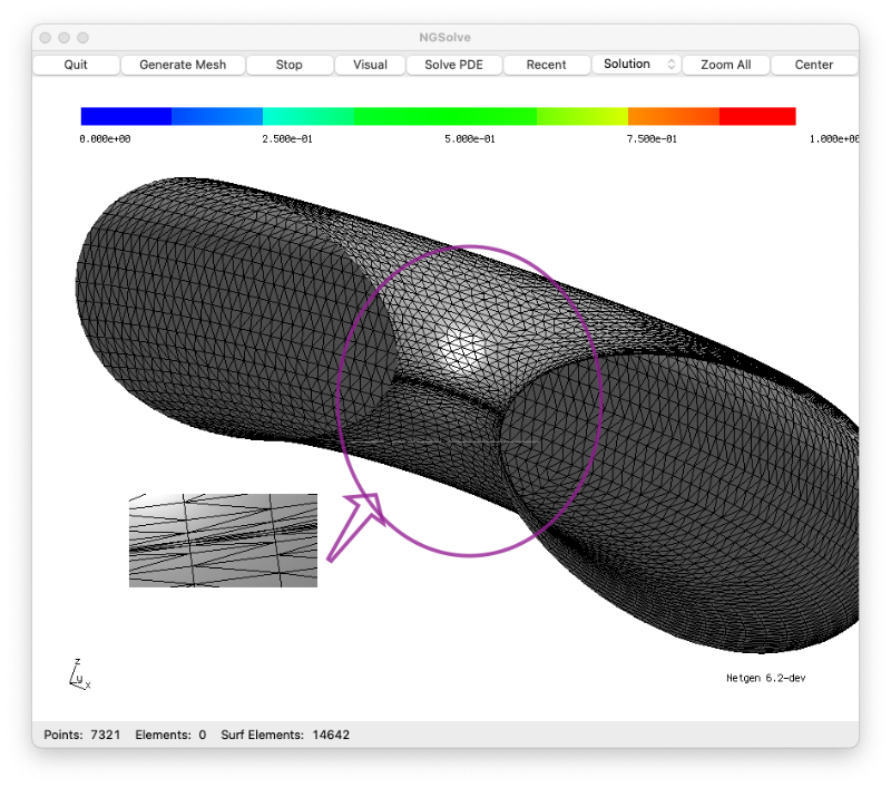 (I have put too many pieces there in order to make the piecewise cubic approximation accurate...) Is there any way to improve the situation?
3. Is the high order space with curved mesh actually the isotropic finite element? or equivalent?
4. Any other suggestions for generating this rotational geometry so that I can use high order isotropic finite element method on surface? I see the recent post on the open cascade. Can it be used to generate my geometric object more precisely?
Thanks in advance.
Jiashun
I am working on a project concerning the meaning curvature flow of a 2d closed surface. Now I am going to perform a numerical test on a rotational geometry which is known as the Angenent Torus, whose profile curve (which is not a circle) can only be numerically computed.
I generate the geometry following this post: Rotationally symmetric geometries .
Thus, I only need to approximate the profile curve in cubic splines.
I choose the control points by guessing:
FIrst I add several nodes of the profile curve, then I compute the intersection of the tangent lines of two adjacent nodes as the additional control nodes.
For example, A1, A2 are two adjacent nodes and I choose B1 as the intersection of their tangent lines. Then I add a cubic spline for example by geo.Append(["spline3",A1,B1,A2]).
I approximate the profile curve by about 40 piecewise cubic splines. (I think more pieces can give high accuracy?) and generate the high order isotropic finite element by using
mesh.curve(2)
and
fes = H1(mesh,order=2)
and begin my computation. However, it seems that this kind of generation is not accuracy enough. The reason that I generate the geometry object first is the "curve" option of mesh needs geometrical information.
My questions:
1. In generating Torus mesh in this post Rotationally symmetric geometries
eps = r*1e-2
# define the control points
pnts = [ (0,R-r), (-r+eps,R-r+eps), (-r,R),
(-r+eps,R+r-eps), (0,R+r), (r-eps,R+r-eps), (r,R), (r-eps,R-r+eps) ]
The introduction of eps seems necessary (why?). Actually, in my case, when using more pieces of splines, I also need to use smaller eps (about 2e-7). Is it correct to plus or minus eps in the above snippet? I think it may leads to discontinuity of normal and then curvature at nodes. Shouldn't it be something like
pnts = [ (0,R-r), (-r+eps,R-r+eps), (-r,R),
(-r-eps,R+r-eps), (0,R+r), (r+eps,R+r+eps), (r,R), (r-eps,R-r-eps) ]
2. After using a large number of splines to approximate the profile curve, the generated mesh seems to obey the piecewise property of the geometry and the mesh quality is terrible
3. Is the high order space with curved mesh actually the isotropic finite element? or equivalent?
4. Any other suggestions for generating this rotational geometry so that I can use high order isotropic finite element method on surface? I see the recent post on the open cascade. Can it be used to generate my geometric object more precisely?
Thanks in advance.
Jiashun
Attachments:
Last edit: 4 years 6 days ago by Jiashun.
4 years 2 days ago - 4 years 2 days ago #4037
by Jiashun
Replied by Jiashun on topic Create an Angenent Torus with high accuracy
I found a way to make the approximate geometry more precise.
After generating a high order mesh (Namely, m1) with a curved geometry, I create several Gridfunctions which interpolate the x,y,z coordinates in an integrationrule space.
Thanks to the command: IntegrationRuleSpaceSurface(mesh, order=InterpolateOrder, definedon=mesh.Boundaries('.*'))
Then I map these coordinates to the nearest points on the "exact but numerical" surface.
Then I transform the displacement from the integrationrulespace to the ordinary H1 space on m1 by an L2 projection.
Let us denote the Gridfunction of displacement as d1.
Then the preciser approximate geometry is obtained by using
m1.SetDeformation(d1).
This leads to smaller errors in geometric quantities such as mean curvature and normal vector.
My question is whether I can save the deformed mesh as a new one, namely, m2.
Since later I need to set deformation on m2, and finally I want to return to m2 by an unSetDeformation command. Now I have to do
m1.SetDeformation(d1) >>>>> generate m2
m1.SetDeformation( something like d1+d2) >>>>> Deform m2 by d2
m1.SetDeformation(d1) >>>>> return to m2
Thanks
Jiashun
Last edit: 4 years 2 days ago by Jiashun.
4 years 1 day ago #4040
by joachim
Replied by joachim on topic Create an Angenent Torus with high accuracy
Hi Jiashun,
you figured out already a lot")
This
does not actually change the mesh, but it stores the mesh and the gridfunction. If you want to save, you have to save both.
Here is an alternative: We have a very new interface to the OpenCascade geometry kernel, which supports also high order spline curves, and and allows to revolve them:
Maybe this is useful for you to build the Angenent Torus.
Best, Joachim
you figured out already a lot
This
Code:
mesh.SetDeformtion(gridfunction)
Here is an alternative: We have a very new interface to the OpenCascade geometry kernel, which supports also high order spline curves, and and allows to revolve them:
Code:
from ngsolve import *
from netgen.occ import *
from math import sin, cos, pi
def Curve(t): return Pnt(0, 3+1.5*cos(t), sin(t))
n = 100
pnts = [Curve(2*pi*t/n) for t in range(n+1)]
spline = SplineApproximation(pnts, 1e-4)
f = Face(Wire(spline))
torus = f.Revolve(Axis((0,0,0), Z), 360)
mesh = Mesh(OCCGeometry(torus).GenerateMesh(maxh=0.3))
mesh.Curve(3)
Draw (mesh)
Maybe this is useful for you to build the Angenent Torus.
Best, Joachim
Attachments:
Time to create page: 0.168 seconds