- Thank you received: 0
Second order meshing of 2D domains (with multiple subdomains)
- bhaveshshrimali
-
Topic Author
- Offline
- Junior Member
-

Less
More
5 years 2 months ago #2887
by bhaveshshrimali
Hi everyone,
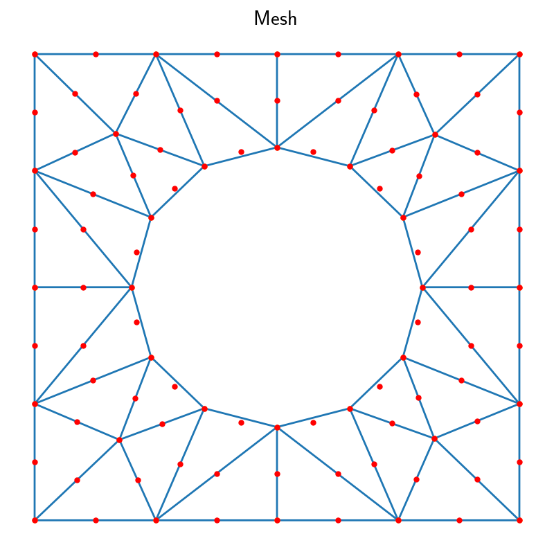
I was trying to generate a second order mesh for a domain comprising of a circle inside square. But was facing an issue. Here is the MWE with a very coarse mesh to delineate the problem:
This, however, generates a mesh where the mid-points of the edges along the circle aren't properly placed. I am guessing it has to do with how I am defining the geometry
Any suggestions on what could be going wrong.
Thank you
I was trying to generate a second order mesh for a domain comprising of a circle inside square. But was facing an issue. Here is the MWE with a very coarse mesh to delineate the problem:
Code:
from ngsolve import *
from netgen.geom2d import SplineGeometry
periodic = SplineGeometry()
pnts = [ (0,0), (1,0), (1,1), (0,1) ]
pnums = [periodic.AppendPoint(*p) for p in pnts]
top = periodic.Append( ["line", pnums[2], pnums[3]], bc="outer")
right = periodic.Append ( ["line", pnums[1], pnums[2]], bc="periodic")
btom = periodic.Append( ["line", pnums[1], pnums[0]], leftdomain=0, rightdomain=1, copy=top, bc="outer")
left = periodic.Append( ["line", pnums[0], pnums[3]], leftdomain=0, rightdomain=1, copy=right, bc="periodic")
# adding the circle
periodic.AddCircle((0.5, 0.5), 0.3, leftdomain=0, rightdomain=1, bc = "inner")
msh = periodic.GenerateMesh(maxh=5)
msh.SecondOrder()
This, however, generates a mesh where the mid-points of the edges along the circle aren't properly placed. I am guessing it has to do with how I am defining the geometry
Any suggestions on what could be going wrong.
Thank you
Attachments:
- bhaveshshrimali
-
Topic Author
- Offline
- Junior Member
-

Less
More
- Thank you received: 0
5 years 2 months ago - 5 years 2 months ago #2888
by bhaveshshrimali
Replied by bhaveshshrimali on topic Second order meshing of 2D domains (with multiple subdomains)
[attachment=undefined]paraview_Ordered.png[/attachment]I think I confused `triplot` of the corresponding linear mesh with the actual mesh. However I noticed something. The ordering of vertices is slightly different than what one would expect in Paraview (vertices followed by edge midpoints in the same order as the vertices)
For instance:
when fed to paraview gives:
whereas adjusting the last 2 points as
gives the desired ordering
[attachment=undefined]paraview_Ordered.png[/attachment]
For instance:
Code:
points = []
cell_arr = []
for pt in msh.Points():
points.append([*pt])
points = np.array(points)
for elem in msh.Elements2D():
cell_arr.append([int(str(i)) for i in elem.points])
points = points[:, :2]
cell_arr = np.array(cell_arr, int)-1
Attachment not found
whereas adjusting the last 2 points as
Code:
cell_arr = cell_arr[:, [0,1,2,5,3,4]] #the last three points are ordered different than what one would expect
gives the desired ordering
[attachment=undefined]paraview_Ordered.png[/attachment]
Last edit: 5 years 2 months ago by bhaveshshrimali.
Time to create page: 0.118 seconds


